Surge Protector Wiring Diagram - Professional Lightning Protection Answer
Surge protector, also called lightning arrester, is an electronic device that provides safety protection for various electronic equipment, instruments and meters, and communication lines. When a spike current or voltage suddenly occurs in an electrical circuit or communication line due to external interference, the surge protector can conduct and shunt in a very short time, thereby avoiding damage to other equipment in the circuit caused by the surge. The following is a detailed description of the "surge protector wiring diagram".
1. How to connect a surge protective device
Installation method of surge protection device wiring:
(i) Surge protectors at all levels of the power supply line should be installed at the entrance of the line into the building, the interface of the lightning protection zone, and near the protected equipment. The connecting wires of surge protectors at all levels should be short and straight, with a length not exceeding 0.5m, and should be firmly fixed. The connection terminals of the surge protector should be connected to the same-name end phase line of the line in the distribution box at the lower pile head of the switch and fuse at this level, and the grounding terminal of the surge protector should be connected to the equipotential grounding terminal board in the lightning protection zone at the shortest distance. The protective grounding wire (PE) of the distribution box should be directly connected to the equipotential grounding terminal board.
(II) The surge protector of the power line with the terminal block should be crimped; the surge protector with the terminal block should be connected with the terminal block by the terminal block.
Different occasions have different power requirements, so many power supply systems are derived. In addition to the common single-phase system, there are also TT system, TN-C system, TN-S system, etc.
Therefore, different models of surge protectors have been developed to correspond to these power supply systems.
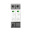
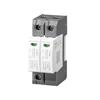
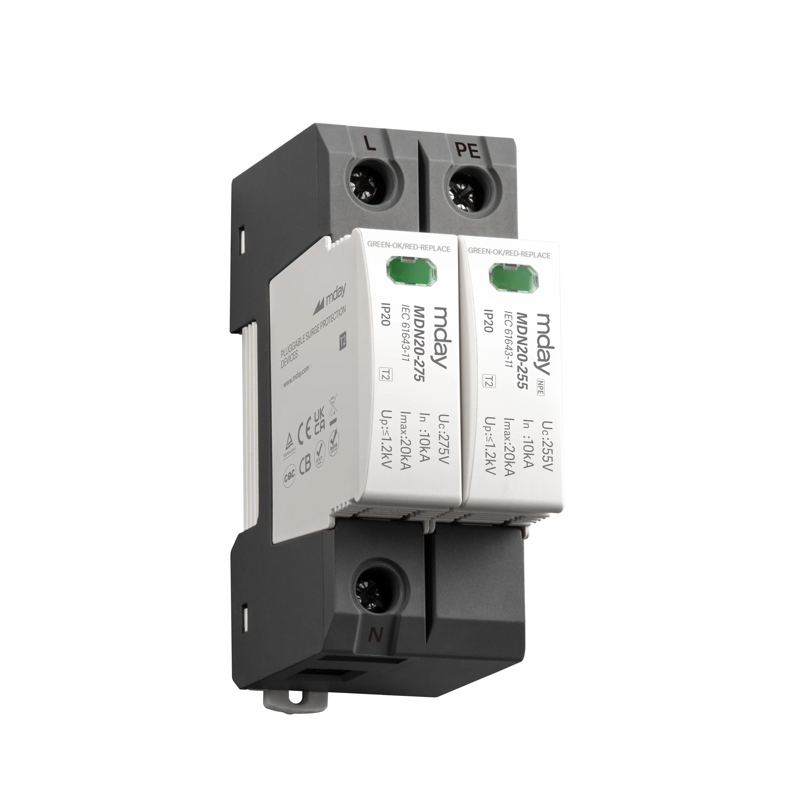
The wiring of the surge protector in the single-phase system, the 2P surge protector is designed as a standard, single-phase three-wire, the upper two holes L port connects the live wire, the N port is the ground wire, and the lower PE port is the ground wire.
The wiring of the surge protector in the TT system, the TT system is a system in which the power system is directly grounded. The grounding of the exposed conductive part of the equipment is electrically unrelated to the grounding of the power system.
The wiring of surge protector in TN-C system, TN-C system is a system that completely shares the protection neutral line and the working neutral line of the trunk line, which is suitable for places without explosion hazard and good safety conditions.
The wiring of surge protector in TN-S system, TN-S system is a system with a functional protection neutral line, that is, the protection neutral line and the working neutral line are completely separated, which is suitable for places with greater danger or higher safety requirements.


