Lightning Protection Design Of Power Supply System
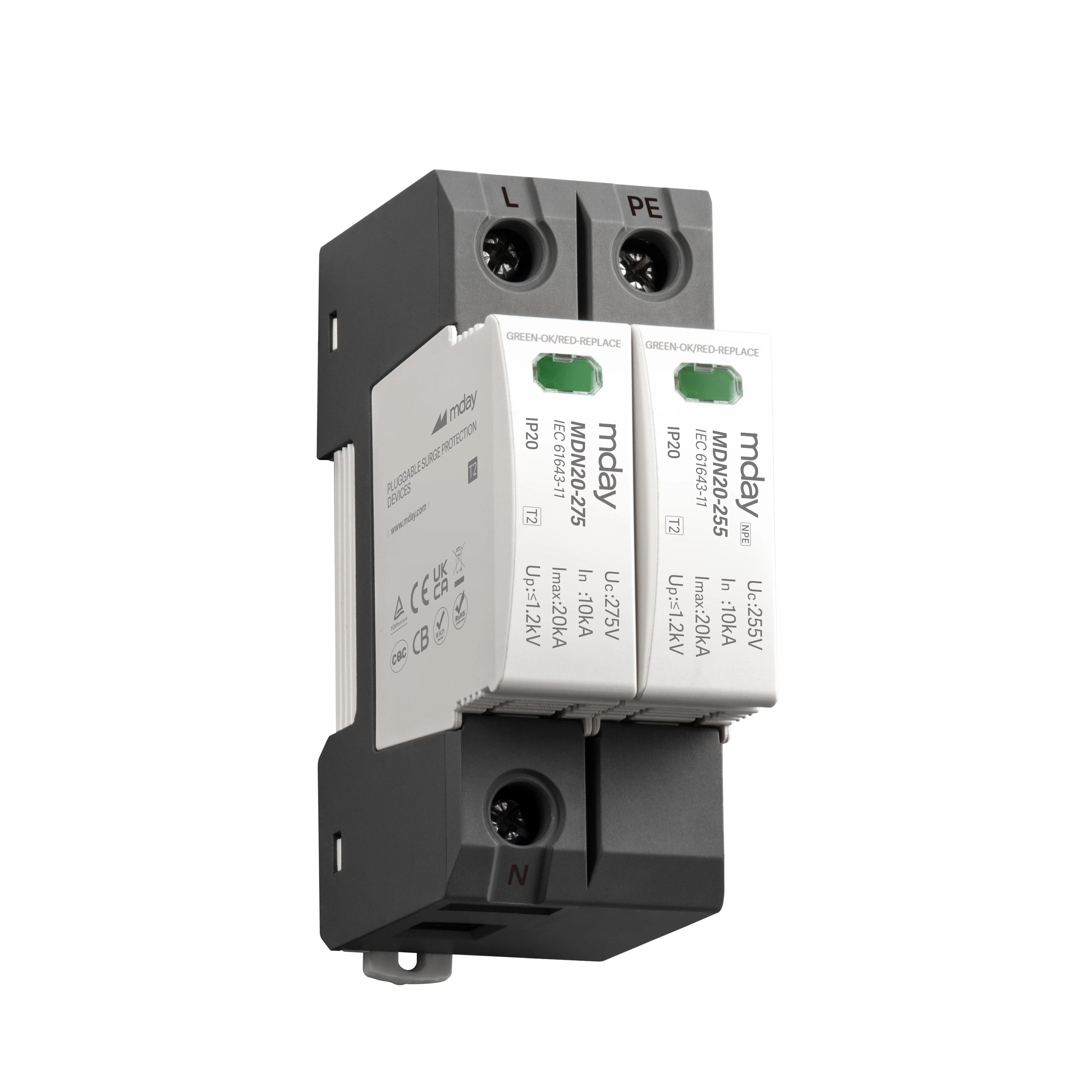
(2) UPS protection. Install a V20-C module between each phase line and the neutral line, install an air switch in front of each module, and install a V20-C/NPE module between the N line and the ground line.
(3) Important equipment end that needs protection. Use CNS32D to protect its power line.
(4) Power protection of weak current equipment. Use V20-C lightning protection module or VF series power fine protection module.
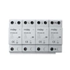
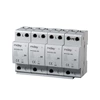
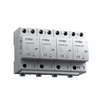
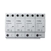
The schematic diagram of the power supply lightning arrester is shown in Figure 1, where MC50-B/3+NPE is a combination of 3 high-energy graphite gap lightning arresters and 1 MC125-B/NPE module, and V20-C/3+NPE/AS is an enhanced lightning arrester with sound and light functions. The lightning arrester and air switch are installed next to the corresponding MB.


