How To Install A Surge Protector
1. General installation requirements of Surge protector
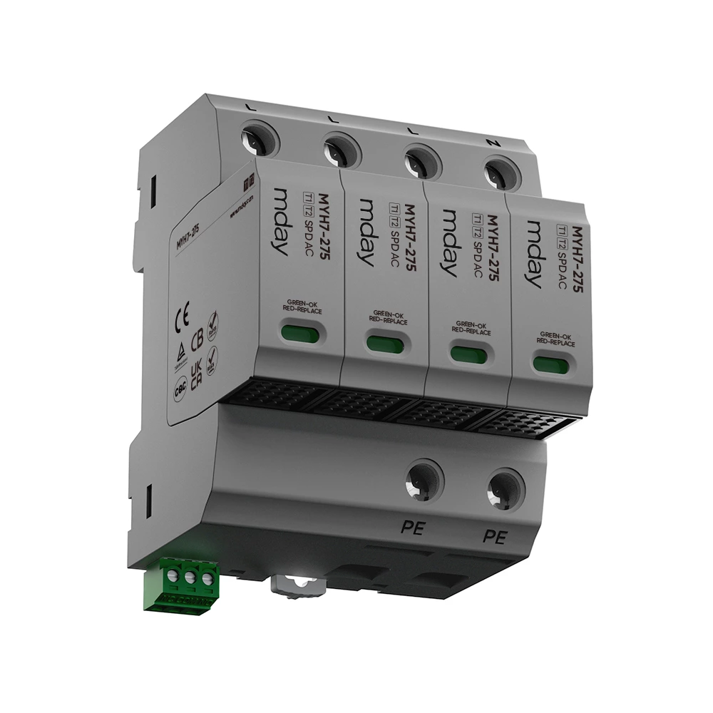
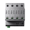
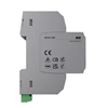
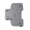
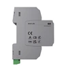
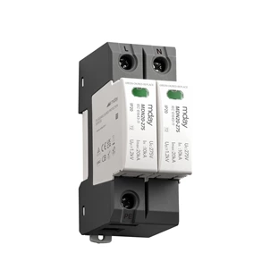
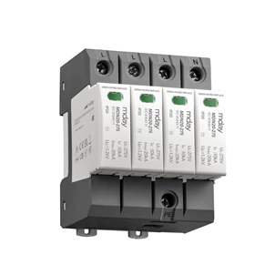
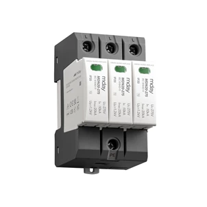
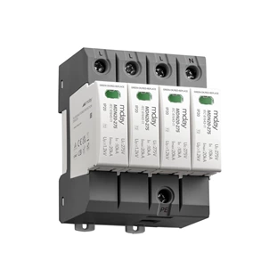
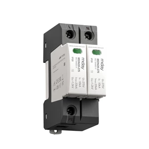
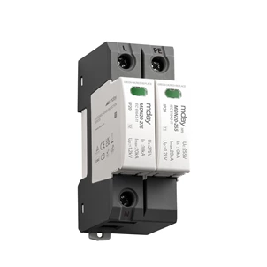
The surge protector is installed using a 35MM standard rail
For fixed SPDs, general installation should follow the following steps:
1) Determine the discharge current path
2) Mark the wires that cause additional voltage drop at the device terminals.
3) To avoid unnecessary inductive loops, the PE conductor of each device should be marked.
4) Establish an equipotential connection between the device and the SPD.
5) Energy coordination of multi-level SPDs is required
In order to limit the inductive coupling between the protected part and the unprotected device part after installation, certain measurements are required. Mutual inductance can be reduced by separating the inductive source from the sacrificial circuit, selecting the loop angle, and limiting the closed loop area.
When the current-carrying component conductor is part of a closed loop, the loop and induced voltage are reduced due to the proximity of this conductor to the circuit.
In general, it is better to separate the protected conductor from the unprotected conductor, and it should be separated from the ground wire. At the same time, necessary measurements should be made to avoid transient orthogonal coupling between power cables and communication cables.
2. SPD grounding wire diameter selection
Data line: required to be greater than 2.5mm2; when the length exceeds 0.5m, it is required to be greater than 4mm2. YD/T5098-1998.
Power line: when the phase line cross-sectional area S≤16mm2, the ground line uses S; when the phase line cross-sectional area is 16mm2≤S≤35mm2, the ground line uses 16mm2; when the phase line cross-sectional area S≥35mm2, the ground line requires S/2; GB 50054 Article 2.2.9
