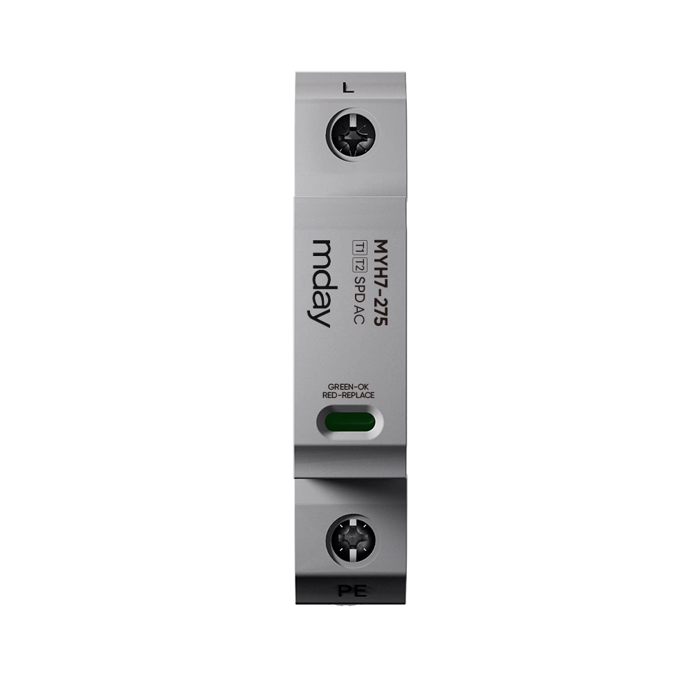
Basic Components Of Surge Protector
Basic Components Of Surge Protector
⒈Discharge gap (also known as protection gap):
It is generally composed of two metal rods exposed to the air with a certain gap between them. One of the metal rods is connected to the power phase line L1 or the neutral line (N) of the equipment to be protected, and the other metal rod is connected to the ground line (PE). When the instantaneous overvoltage strikes, the gap is broken down, and part of the overvoltage charge is introduced into the earth, avoiding the voltage increase on the protected equipment. The distance between the two metal rods of this discharge gap can be adjusted as needed, and the structure is relatively simple. Its disadvantage is poor arc extinguishing performance. The improved discharge gap is an angular gap, and its arc extinguishing function is better than the former. It extinguishes the arc by the action of the electromotive force F of the circuit and the rising action of the hot air flow.
⒉Gas discharge tube:
It is composed of a pair of cold cathode plates separated from each other and encapsulated in a glass tube or ceramic tube filled with a certain inert gas (Ar). In order to increase the triggering probability of the discharge tube, there is also a triggering agent in the discharge tube. This type of gas-filled discharge tube has two-pole and three-pole types.
The technical parameters of the gas discharge tube are mainly: DC discharge voltage Udc; impulse discharge voltage Up (usually Up≈(2~3)Udc; power frequency withstand current In; impulse withstand current Ip; insulation resistance R (>109Ω); inter-electrode capacitance (1-5PF)
The gas discharge tube can be used under DC and AC conditions. The selected DC discharge voltage Udc is as follows: Used under DC conditions: Udc≥1.8U0 (U0 is the DC voltage of the normal operation of the line)
Used under AC conditions: U dc≥1.44Un (Un is the effective value of the AC voltage for normal operation of the line)
⒊Varistor:
It is a metal oxide semiconductor nonlinear resistor with ZnO as the main component. When the voltage applied to its two ends reaches a certain value, the resistor is very sensitive to voltage. Its working principle is equivalent to the series and parallel connection of multiple semiconductor P-N. The characteristics of the varistor are good nonlinear characteristics (nonlinear coefficient α in I=CUα), large current capacity (~2KA/cm2), small normal leakage current (10-7~10-6A), low residual pressure (depending on the varistor The working voltage and current capacity of the varistor are fast (~10-8s) in response to transient overvoltage, and there is no continuous current.
The main technical parameters of the varistor are: varistor voltage (i.e. switching voltage) UN, reference voltage Ulma; residual voltage Ures; residual voltage ratio K (K=Ures/UN); maximum current capacity Imax; leakage current; response time.
The conditions for the use of the varistor are: varistor voltage: UN≥[(√2×1.2)/0.7]U0 (U0 is the rated voltage of the power supply)
Minimum reference voltage: Ulma≥(1.8~2)Uac (Used under DC conditions)
Ulma≥(2.2~2.5)Uac (Used under AC conditions, Uac is the AC working voltage)
The maximum reference voltage of the varistor should be determined by the withstand voltage of the protected electronic equipment, and the residual voltage of the varistor should be lower than the loss voltage level of the protected electronic equipment, that is, (Ulma)max≤Ub/K, where K is the residual voltage ratio and Ub is the loss voltage of the protected equipment.
⒋ Suppression diode:
The suppression diode has a clamping voltage limiting function. It works in the reverse breakdown region. Because it has the advantages of low clamping voltage and fast action response, it is particularly suitable for use as the last few levels of protection components in a multi-level protection circuit. The volt-ampere characteristics of the suppression diode in the breakdown region can be used as follows Formula: I=CUα, where α is the nonlinear coefficient, for Zener diodes α=7~9, for avalanche diodes α=5~7.
Technical parameters of suppression diodes
Breakdown voltage, it refers to the breakdown voltage under the specified reverse breakdown current (usually lma), the rated breakdown voltage of Zener diodes is generally in the range of 2.9V~4.7V, and the rated breakdown voltage of avalanche diodes is often in the range of 5.6V~200V.
⑵Maximum clamping voltage: it refers to the highest voltage that appears at both ends of the tube when a large current of a specified waveform passes through it.
⑶Pulse power: it refers to the product of the maximum clamping voltage at both ends of the tube and the current in the tube under the specified current waveform (such as 10/1000μs).
⑷Reverse displacement voltage: it refers to the maximum voltage that can be applied to both ends of the tube in the reverse leakage region, at which the tube should not break down. This reverse displacement voltage should be significantly higher than the highest operating voltage peak of the protected electronic system, that is, it cannot be in a weak conduction state when the system is operating normally.
⑸Maximum leakage current: It refers to the maximum reverse current flowing through the tube under the action of the reverse displacement voltage.
⑹Response time: 10-11s
⒌Choke coil: The choke coil is a common-mode interference suppression device with ferrite as the magnetic core. It consists of two coils of the same size and the same number of turns symmetrically wound on the same ferrite ring magnetic core to form a four-terminal device. It should have a large inductance to suppress the common-mode signal, and a very small leakage inductance to the differential mode signal. The choke coil can effectively suppress the common-mode interference signal (such as lightning interference) in the balanced line, and has no effect on the differential mode signal transmitted normally in the line.
The choke coil should meet the following requirements when making it
1) The wires wound on the coil core should be insulated from each other to ensure that there is no breakdown short circuit between the turns of the coil under the action of transient overvoltage.
2) When a large instantaneous current flows through the coil, the magnetic core should not be saturated.
3) The magnetic core in the coil should be insulated from the coil to prevent breakdown between the two under the action of instantaneous overvoltage.
4) The coil should be wound in a single layer as much as possible, which can reduce the parasitic capacitance of the coil and enhance the coil's ability to withstand instantaneous overvoltage.
⒍ 1/4 wavelength short circuit device
The 1/4 wavelength short circuit device is a microwave signal surge protector made based on the spectrum analysis of lightning waves and the standing wave theory of antenna feed lines. The length of the metal short-circuit rod in this protector is determined by the size of 1/4 wavelength of the working signal frequency (such as 900MHZ or 1800MHZ). For the working signal frequency, the impedance of this parallel short-circuit rod length is infinite, which is equivalent to an open circuit and does not affect the transmission of the signal. However, for lightning waves, since the lightning energy is mainly distributed below n+KHZ, the impedance of this short-circuit rod for lightning waves is very small, which is equivalent to a short circuit, and the lightning energy level is discharged into the ground.
Since the diameter of the 1/4 wavelength short-circuit rod is generally a few millimeters, it has good impact current resistance performance, which can reach more than 30KA (8/20μs), and the residual voltage is very small. This residual voltage is mainly caused by the inductance of the short-circuit rod itself. Its disadvantage is that the power frequency band is narrow, with a bandwidth of about 2% to 20%. Another disadvantage is that it cannot add DC bias to the antenna feed facilities, which limits some applications.
