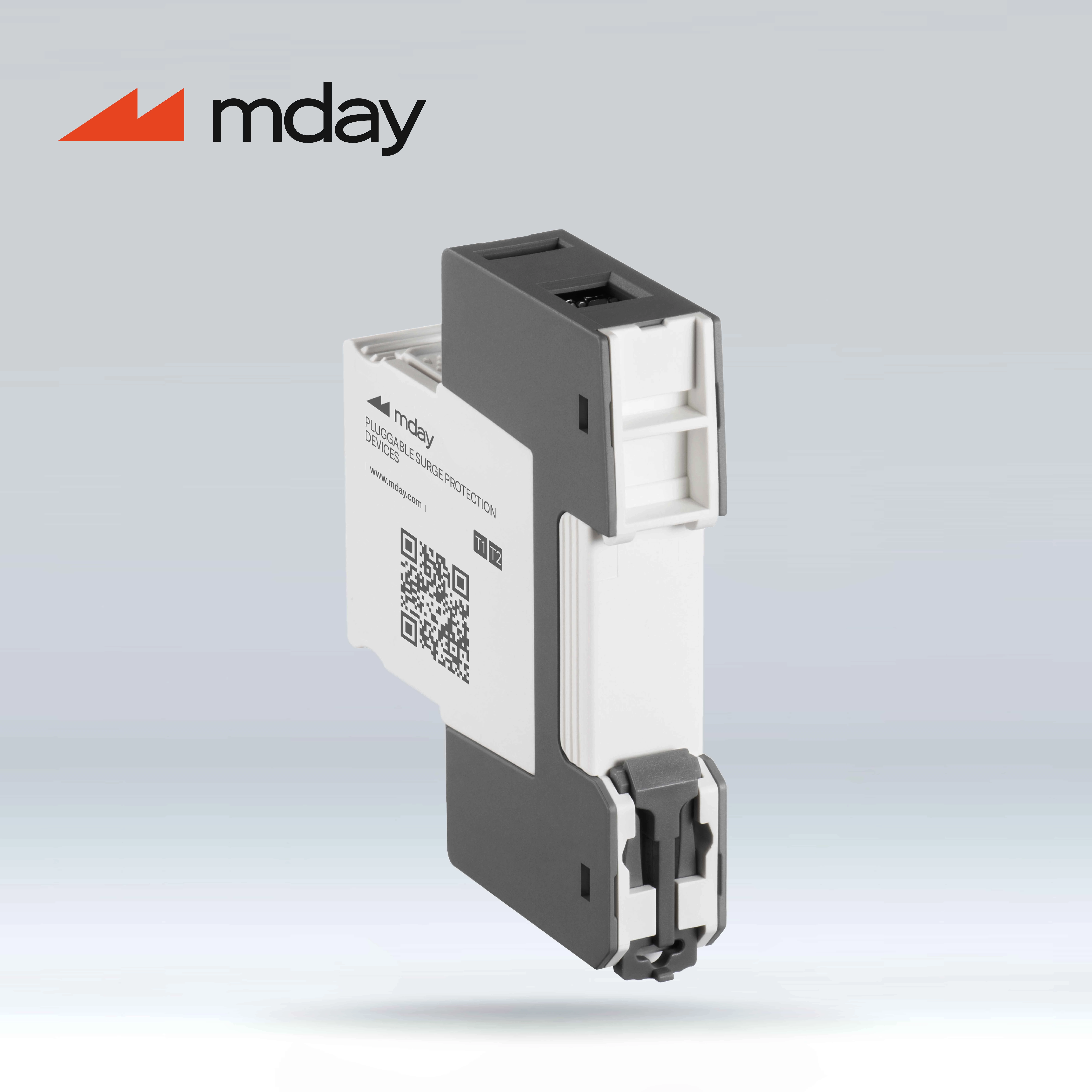
Application Scenarios Of Spd Surge Protector
Application scenarios of SPD surge protectors,The IEC 61643 product standard divides the applications in which surge protective device are used into low-voltage systems, telecommunications and signal processing networks, and photovoltaic installations. In general, all areas have different individual system prerequisites. Accordingly, all the solutions or steps involved can vary significantly, so it is worth examining these applications in more detail.
6.1 Protection of AC systems
6.1.1 SPD types and technologies
Application scenarios of SPD surge protection device,The lightning protection zone concept provides coordinated surge protection devices for all lines across a zone, whose power values are based on the protection level to be achieved.
Depending on the zone transition, different types are therefore required. The requirements for the various SPD types are defined in the product standard IEC 61643-11 [6] for surge protection devices.
Application scenarios of SPD surge protectors,The multi-level function limits the lightning protection level between zones. The amplitude and specific energy of the expected surge voltage or surge current are gradually reduced. The voltage value to which the individual SPDs must limit the surge voltage is also reduced. This is achieved by correspondingly low voltage protection levels: their upper limit is based on the dielectric strength of the nearby equipment to be protected.
Type 1 surge protection devices must meet the highest requirements in terms of amplitude and specific energy of the surge voltage or surge current, because they should protect against direct lightning strikes. In typical installation environments for main power distribution, the requirements for short-circuit withstand capability are often very high, and in order to be able to meet these requirements, powerful technologies such as spark gap technology are required.
The operating principle of a spark gap is initially very simple: two electrodes are placed at a specific distance from each other and form an insulating state. If there is a voltage between the two electrodes, causing the dielectric strength of the air in this space (approximately 3 kV/mm) to exceed the surge voltage, an arc is formed. The impedance of the arc is very low compared to the insulating state, where the impedance is in the gigaohm range, and therefore, so is the voltage drop across the spark gap.
Application scenarios of SPD surge protectors, this characteristic is very suitable for discharging lightning currents: the lower the residual voltage of the spark gap, the lower the energy input that needs to be managed. Regarding the sudden change in impedance, and therefore also the voltage difference across the spark gap, the nonlinear characteristic is called voltage switching. A significant advantage of low residual voltage is the lower load on the protected equipment due to the voltage being higher than the specified nominal voltage or maximum continuous voltage. For longer lightning current durations, the residual voltage of the spark gap is low, within the maximum continuous voltage of the protected device. Type 1 SPDs with voltage-limiting components are usually hundreds of volts higher than this - the load on the protected equipment is much greater.
Modern spark gaps are usually enclosed in a sturdy closed steel housing, so that during the discharge, the ionized gases produced by the arc do not leak into the environment. In addition, spark gaps are often triggered: they have additional wiring to support the full ignition of the spark gap. This limits the voltage protection level to a very low level - significantly lower than the voltage generated based on the dielectric strength of air. Even if the installation environment of type 1 SPDs is generally not required, the voltage protection level of modern triggered spark gaps is usually at the level of the lowest overvoltage category I (based on the nominal voltage of the system).
Application scenarios of SPD surge protectors, a special feature of spark gaps is the continuous current extinguishing capability, Ifi. If a spark gap is ignited by a surge voltage, it represents a short circuit, driving current for the connected power network. Therefore, the spark gap must be able to interrupt the power current by itself after the discharge process without triggering the upstream overcurrent protection device. The sequential current extinguishing capability indicates under what circumstances the expected short-circuit current installation position can be guaranteed. Modern spark gaps must be able to do two things:
• Release a large amount of energy from a short-lived lightning current
• Independently eliminate continuous current from a powerful power supply network
Application scenarios of SPD surge protectors,In the case of lightning currents, in the best case, the impedance of the spark gap is very low to keep the energy input as low as possible and increase robustness. However, in the case of continuous currents, the impedance must be as high as possible to ensure rapid elimination. In order to withstand lightning current amplitudes of up to 50 kA on power supply networks with possible short-circuit currents of up to 100 kA. Therefore, today's spark gaps are usually complex in structure and consist of many individual functional components.
6.1.3 Type 2: Surge Protector
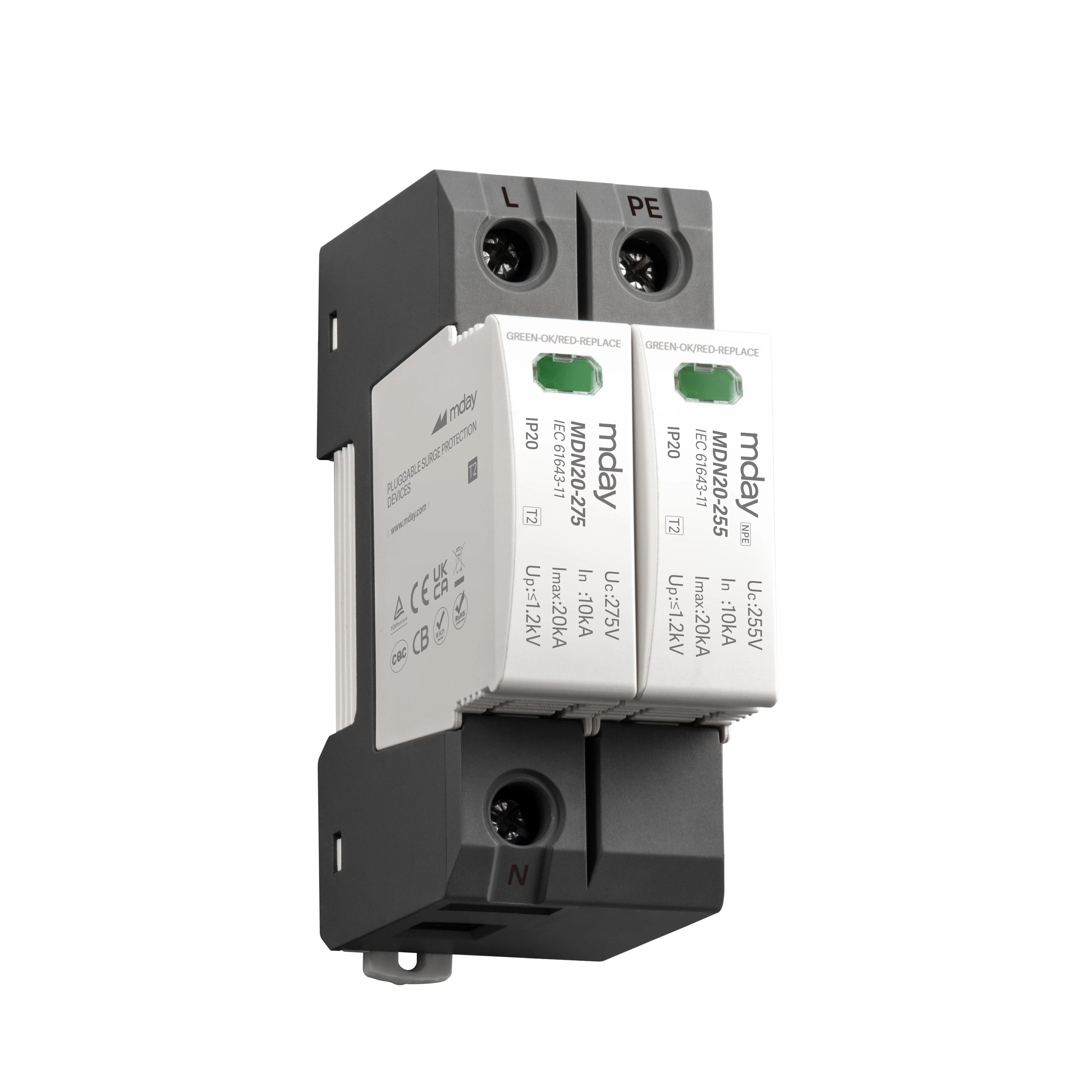
Application scenarios of SPD surge protectors, Type 2 surge protective devices are usually installed in sub-distribution or machine control cabinets. These SPDs must be able to discharge induced surge voltages caused by indirect lightning strikes or switching operations, but cannot handle direct lightning strikes. As a result, the energy input is significantly reduced. In any case, the induced surge voltage caused by switching operations is usually very dynamic. Here, discharge technologies with fast response behavior stand the test, such as varistor technology.
Application scenarios of SPD surge protectors, Varistors (variable resistors or metal oxide varistors, MOVs) are semiconductor components made of metal oxide ceramics. They exhibit a nonlinear current-voltage characteristic curve. In the low voltage range, the impedance of the varistor is very high, but in the higher voltage range, the impedance drops rapidly, so that very large currents can be discharged without problems. Therefore, the characteristics of the varistor are called voltage-limiting characteristics. Due to the typical response time in the lower nanosecond range, varistors are even very suitable for limiting particularly dynamic surge voltage phenomena.
High-performance varistors can even demonstrate a pulse discharge capacity of up to 12.5 kA (10/350 μs), which means that they are also suitable as a type 1 SPD for environments with low protection levels.
For higher pulse discharge capacities of 25 kA to 50 kA (10/350 μs), multiple varistors must usually be used in parallel. Surge protection manufacturers without spark gap technology therefore often use varistors as type 1 SPDs of lightning protection level
I. This concept has serious disadvantages: if the characteristics of the parallel varistors are not precisely matched, the requirements are difficult to meet and during operation, the individual paths are placed under different loads. Over time, the uneven load becomes greater and greater. This ultimately leads to an overload of the varistor.
6.1.4 Type 3: Equipment protection
Application scenarios of SPD surge protectors, type 3 surge protectors are generally installed directly in front of the protected terminal equipment. Due to different installation environments, the design range of type 3 SPDs is very wide. For example: In addition to the standard DIN rail mounting, there are devices for mounting in sockets or directly on the PCB of the terminal device.
Technically, type 3 SPDs are most similar to type 2, which is based on varistors, but have lower requirements in terms of nominal discharge capacity than type 2. It is common to link the power supply protection to the protection of other interfaces in the terminal device, such as data communication lines. There are combined devices for this purpose. They protect all corresponding (power supply) lines against surges.
6.1.5 Coordination of different types of SPDs
Application scenarios of SPD surge protectors, lightning protection zone concepts provide coordinated surge protection devices for all lines across a zone. Their power value is based on the protection level to be achieved. Depending on the zone transition, different types are therefore required. The requirements for the various SPD types are defined in the product standard IEC 61643-11 [6] for surge protective devices. Multi-stage protection concepts can be derived from this.
Starting from the inner protection zone, a type 3 SPD and an upstream type 2 SPD are coordinated. It must be ensured that the type 3 SPD is not overloaded in terms of energy. Since surge voltages of lower amplitude are expected in this area of the protection zone concept, selective addressing is already ensured by the Uc of the type 3 SPD, which is greater than or equal to that of the type 2 SPD.
Application scenarios of SPD surge protectors,In the direction of the external protection zone, the coordination between the type 2 SPD and the upstream type 1 SPD must be ensured again. Since the possibility of a direct lightning strike or a partial lightning strike must be considered here, which can only be borne by the type 1 SPD, the selective addressing of the SPD is particularly important, otherwise the type 2 SPD may be overloaded. Since the technology used for type 1 SPDs is very different, there are no universal coordination conditions. Type 1 SPDs based on spark gaps have a clear advantage in this regard. Their relatively low residual voltage of only a few hundred volts during most of the lightning current ensures an almost complete conversion of the current.
6.1.6 Grid systems in accordance with IEC 60364
Application scenarios of SPD surge protectors, the design of surge protection concepts for AC systems depends on the existing grid systems, among other things. These systems can vary depending on the grounding design of the transformer that provides the power, the power consumption system and the connection between them. The directive IEC 60364-1 [10] for erecting low-voltage power supply systems lists the following system configurations:
In this grid system, one point of the supply transformer - usually the neutral point - is usually directly grounded. The neutral conductor (N) and the protective conductor (PE) are connected to the power consumption system in separate conductors. The three-phase power supply consists of five conductors: L1, L2, L3, N and PE.
In this grid system, the neutral point of the supply transformer is directly grounded. The neutral conductor and the protective conductor are connected to the power consumption system via one conductor (PEN). The three-phase power supply consists of four conductors: L1, L2, L3 and PEN.
In this grid system, the grounding point of the transformer is connected to the system only as a neutral conductor. The various parts of the electrical system are connected to a local grounding system that is separate from the transformer grounding point. The neutral conductor and the local protective conductor are connected to the power consumption system through separate conductors. The three-phase power supply consists of five conductors: L1, L2, L3, N and local PE.
In this power grid system, the neutral point of the supply transformer is not grounded, or is only grounded through a high impedance. The various parts of the electrical system are connected to a local grounding system that is separate from the transformer grounding point. If the neutral conductor is also wired from the neutral point of the transformer that provides energy, this neutral conductor is wired separately from the local protective conductor. The three-phase power supply consists of four or five conductors: L1, L2, L3 (if applicable) and local PE.
Application scenarios of SPD surge protectors, a feature of IT systems is that insulation faults to ground may occur in a limited time. This phase-to-ground fault only needs to be detected and reported by insulation monitoring for timely correction. Only when a second ground fault occurs will it cause a short circuit between the two phases and the relevant surge protection device will trip. Therefore, the surge protector used for IT systems must be able to withstand the phase-to-phase voltage of the system as well as the tolerance. This is ensured by the specification requirement that only SPDs with a maximum continuous voltage of at least the phase-to-phase voltage plus a tolerance can be used between phases and PE in IT systems.
